Dynamic Load Testing for Piles: DLT vs PDA Testing and How Signal Matching Software Works
- Gadi Lahat
- May 5
- 8 min read

Quick Answer: Dynamic Load Testing (DLT) is the complete test procedure used to verify pile bearing capacity on site. The PDA (Pile Driving Analyzer®) is the instrument that collects real-time force and velocity data during the test. Signal matching is the post-processing software that turns that raw field data into a defensible static capacity result. All three are part of the same high-strain dynamic testing workflow — and each one plays a distinct, essential role.
If you are involved in deep foundation construction or geotechnical engineering, you have almost certainly encountered the terms dynamic load testing, PDA pile testing, and CAPWAP® signal matching. These are frequently used interchangeably — but they are not the same thing.
Understanding the difference between a DLT test, a PDA test, and signal matching analysis is critical for specifying the right testing programme, interpreting results correctly, and ensuring your foundation meets both engineering and regulatory requirements.
This guide explains exactly what each method does, when to use each one, and how they connect to deliver a complete, ASTM D4945-compliant pile capacity assessment.
What Is Dynamic Load Testing (DLT) for Piles?
Dynamic Load Testing (DLT) is the complete high-strain testing procedure used to evaluate pile bearing capacity, driving stresses, and structural integrity during or after pile installation. It is the overarching test — encompassing sensor installation, data collection, real-time field analysis, and post-processing signal matching to produce a verified static capacity result.
DLT is governed by two internationally recognised standards:
ASTM D4945 — Standard Test Method for High-Strain Dynamic Testing of Deep Foundations
EN ISO-22477-4 — the European equivalent standard for dynamic pile load testing
When a project specification calls for dynamic load testing, it means this entire process must be completed and documented to standard.
When Should Dynamic Load Testing Be Used?
DLT is used whenever a project requires a verified assessment of pile static bearing capacity — either as a standalone test or as a faster, more cost-effective alternative to a traditional static load test. Key use cases include:
Driven pile programmes — confirming capacity during or immediately after installation
Re-strike testing — performed after a waiting period of several days to a week, once soil setup (strength recovery after driving disturbance) has occurred, to determine long-term pile capacity
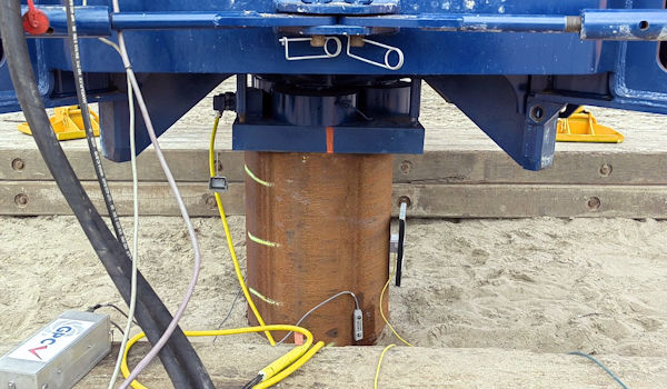
Bored piles and CFA piles — tested using a drop hammer after installation when a conventional driving rig is not available
Production pile verification — testing a statistically representative sample across a large site
Static load test substitution — where physical testing is impractical due to cost, schedule, or site access constraints
Research comparing DLT with static load test results across 51 piles found an average DLT/SLT ratio of 0.98 — confirming strong agreement between the two methods when properly executed.
What Is a PDA ® Test and How Does It Work?
The PDA (Pile Driving Analyzer ®) is the instrument used to capture and process data in the field during a dynamic load test. A PDA test specifically refers to the real-time measurement and analysis phase: attaching sensors to the pile, recording force and velocity signals during hammer driving of the pile into the ground, and computing immediate results using the Case Method to endure the needed capacity load is reached and that the pile was not damaged while driving it into the round
How PDA Testing Works on Site
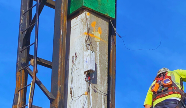
Strain transducers and accelerometers — often combined into a single Comboducer sensor — are attached to the pile at a minimum of two pile diameters below the pile head. These sensors connect to the PDA unit, which conditions the signals and outputs results after every hammer blow.
The Case Method produces immediate, on-site estimates of:
Pile bearing capacity — total shaft resistance plus toe bearing
Hammer energy transfer — the exact energy delivered to the pile per blow, calculated from force and velocity measurements
Compression and tension stresses — at the pile head, toe, and shaft, critical for detecting stress levels that could crack a concrete pile
Pile integrity — by identifying early tension wave returns that indicate a crack or structural defect in the shaft
When Is PDA Monitoring Most Valuable?
Establishing driving criteria — monitoring energy transfer and stress levels during test pile installation to define blow count and refusal criteria for production piles
Real-time integrity monitoring — detecting pile damage as it happens, before more piles are driven with the same equipment configuration
Production pile monitoring — rapid assessment of large pile programs, with immediate field results
Stress verification for concrete piles — especially prestressed concrete, where tension stress during driving can cause invisible internal cracking
What Is CAPWAP ® Signal Matching in Pile Testing?
CAPWAP ® (Case Pile Wave Analysis Program) is signal matching software that post-processes the force and velocity data recorded by the PDA to produce a far more detailed and accurate picture of pile behaviour than the real-time Case Method alone can deliver.
While the Case Method gives immediate field estimates, it relies on an assumed soil damping factor. CAPWAP ® removes that assumption by building a full mathematical model of the pile and soil, then running an iterative simulation to find the soil resistance distribution that best reproduces the measured signals.
How CAPWAP ® Signal Matching Works Step by Step
Force and velocity signals from the PDA test are imported into the software
The pile is modelled as a series of segments — each with defined mass, stiffness, and cross-sectional area
The surrounding soil is modelled using springs (static resistance) and dashpots (dynamic resistance) at every depth increment
The software simulates the stress wave travelling through this model and generates a calculated force signal
The calculated signal is compared to the measured signal from the field
Soil resistance parameters are iteratively adjusted until the two signals match as closely as possible — quantified by a Match Quality number
The final matched model produces the complete capacity result
What CAPWAP ® Signal Matching Produces
Total static bearing capacity — the mobilised pile resistance at the time of testing
Resistance distribution — exactly how much capacity comes from shaft friction at different depth zones versus end bearing at the pile toe
Simulated static load test — a load-settlement curve directly comparable to a physical static load test result
Driving stress maxima — peak compression and tension stresses along the full pile length
This level of detail is what separates a complete DLT from a basic field measurement. AASHTO specifications state that signal matching is a requirement for dynamic load testing — it must be performed on at least one pile per project, and on a representative sample for sites with variable ground conditions.
CAPWAP ® vs N_GAPA: What Piletest Uses
The GPC PDA System from Piletest includes N_GAPA — a built-in automatic signal matching tool that performs the same analysis as CAPWAP ® within the GPC software environment. Engineers move directly from real-time field data capture into signal matching post-processing without switching platforms. N_GAPA has been independently demonstrated to deliver results equal to or better than CAPWAP ®, and is included at no additional cost with the GPC system.

DLT vs PDA ® vs CAPWAP ®: Key Differences at a Glance
| DLT | PDA Test | CAPWAP ® / Signal Matching |
What it is | The complete test procedure | The field instrument and real-time analysis | Post-processing analysis software |
When it runs | The full test event | During hammer impacts on site | After the test, in office or on site |
Output | Verified capacity assessment | Real-time capacity, stresses, integrity | Capacity distribution, simulated SLT |
Standard | ASTM D4945 / EN ISO-22477-4 | Case Method | Signal matching per ASTM D4945 |
Who uses it | Engineer of record / project owner | Field testing engineer | Geotechnical analyst |
DLT is the test. PDA is how you run it. CAPWAP ® signal matching is how you fully understand what the results mean.
How to Detect Pile Damage During High-Strain Dynamic Testing
One of the most practical advantages of real-time PDA monitoring is the ability to detect pile damage as it occurs during installation.
When a hammer strikes the pile, a stress wave travels down to the toe and reflects back. In an intact pile, this tension wave returns at a predictable time based on pile length and wave speed. If the wave returns early — before it should have reached the toe — this early tension return is a clear indicator of a crack, break, or structural discontinuity in the shaft.
Detecting this in real time allows the crew to stop immediately, investigate the cause, and adjust hammer energy or cushion configuration before continuing. This prevents progressive damage and eliminates the risk of discovering a broken pile only after the full programme has been completed.
Which Dynamic Pile Testing Method Does Your Project Need?
Use PDA monitoring during installation when:
You need to establish blow count and refusal criteria for production piles
Driving stress verification is required for concrete or prestressed piles
Real-time integrity checking across a large production pile programme is specified
Use full DLT with CAPWAP ® signal matching when:
Your specification requires a verified static bearing capacity per ASTM D4945
A static load test is required but a cost-effective, technically accepted alternative is needed
Re-strike testing is being performed after soil setup to confirm long-term capacity
Resistance distribution along the pile shaft is needed for design verification
Use both together when:
Test piles are being driven to establish project-wide criteria and capacity confirmation is also required
Variable soil conditions across the site make capacity distribution uncertain
Regulatory or contractual requirements specify dynamic load testing with signal matching on a defined sample
How Piletest Delivers Complete Dynamic Load Testing
The GPC PDA System from Piletest supports the full high-strain dynamic testing workflow in a single integrated platform. The Comboducer sensor combines strain gauge and accelerometer in one unit with single-bolt attachment for rapid site setup. Wireless connectivity enables real-time monitoring from any PC, and the built-in N_GAPA signal matching software delivers CAPWAP ® -equivalent results without additional tools or licensing costs.
The GPC system is fully compliant with ASTM D4945 and EN ISO-22477-4, and comes with a 3-year hardware warranty and 10 years of software support.
For hardware guides, software downloads, calibration certificates, and direct technical assistance, visit the Piletest Support Centre.
Frequently Asked Questions About Dynamic Load Testing
What is the difference between DLT and PDA pile testing?
DLT (Dynamic Load Test) is generic name, it is the full testing procedure — from sensor installation through to final capacity results.
PDA (Pile Driving Analysis) is specific name. It happens to be the brand-name of a trade-marked equipment (Pile Driving Analyzer). People often use this specific name because of its easier pronunciation.
What is signal matching and why is it required?
Signal-matching processes PDA’s force and velocity data to determine static bearing capacity, resistance distribution along the shaft and toe, and a simulated static load test curve.
It is required due to reliable correlation with Static Load Test (SLT) results.
CASE method is not required because it is a preliminary estimate, based on only 1 parameter: Pile Toe CASE damping JC. CASE method result does not have a reliable correlation with Static Load Test results.
Can dynamic load testing (DLT) replace a static load test (SLT)?
Yes for Displacement piles (e.g., concrete piles, timber piles, closed-end pipe piles) and for large diameter non-displacement piles (e.g., open-ended pipe piles larger than 1-m diameter where plugging does not happen), and for any end-bearing piles.
No for small non-displacement frictional piles (e.g., steel H piles, small open-ended pipe piles): Reason: for this small sub-group of frictional piles, during the Dynamic Test, the piles are coring the soils (i.e., no plugging). However, in Static Load Test, plugging is common for small piles. As such, the correlation between DLT and SLT result is poor for this sub-group.
What is an early tension return in PDA data?
A stress wave that reflects back up the pile before reaching the toe — a primary indicator of a crack or structural defect in the pile shaft, detected during real-time PDA monitoring.
When should re-strike pile testing be performed?
After a waiting period of several days to a week following initial installation, allowing soil setup (strength recovery) to occur. Re-strike testing gives a more accurate picture of long-term pile capacity than end-of-drive measurements alone.
What standards govern dynamic load testing?
Dynamic load testing is governed by ASTM D4945 (internationally) and EN ISO-22477-4 (Europe). Both define sensor calibration requirements, test procedures, signal matching requirements, and reporting standards.
Pile Driving Analyzer® and CAPWAP® are registered trademarks of Pile Dynamics Inc.


Comments